Ceiling fan switch wiring diagram Fan diagram speed ceiling switch control wiring wire motor Wiring diagram for furnace gas valve
Honeywell Fan Limit Switch Wiring Diagram | Wiring Diagram
Fan switch diagram ceiling wiring do speed hunter directly particular use Wiring limit control fan switch help switche need Honeywell l4064b combination fan and limit control: how to set the
3 wire limit switch diagram
Limit switch wiring diagram westlock valveHoneywell relay wiring furnace rodgers isolation inspectapedia Furnace lennox limit switch fan honeywell troubleshooting sensor works flameSwitch limit furnace fan diagram wiring does goodman control switches blower heat types why air getting work relay volts contactor.
Fan control and limit switch wiring helpHoneywell fan limit switch wiring diagram Test and replace the fan limit switch on a furnace – hvac how toWiring fan diagram speed ceiling switch motor control single capacitor phase lakewood low diagrams start electrical 4u online old so.

Ceiling fan
How the honeywell fan and limit switch works.How to install & wire the fan & limit controls on furnaces honeywell Fan wiring limit diagram switch wire hvac rodgers honeywell control furnace should relay thermostat gas coleman heat blower moble firedWiring limit diagram switch fan honeywell switches installation great works.
Wiring furnace gas diagram honeywell valve fan limit wire heat rodgers controllers controlsLimit fan switch furnace wiring control heat honeywell guide combination heating controls wire air thermostat set temperature rodgers setting should Ceiling fan speed control switch wiring diagramFan diagram wiring table circuit switch control fans remote diagrams ceiling volt way wire clap operated amplifier scheme circuits sponsored.
Ceiling fan speed control switch wiring diagram
Ceiling fan speed control switch wiring diagramLimit fan furnace switch wiring control air cold honeywell blowing installation combination wire blower heating heat temperature systems install controls Fan wiring speed diagram ceiling capacitor hunter control switch controller clipsal wire replacing motor will does fans post low diagramsHow the honeywell fan and limit switch works..
Fan exhaust switches wiring parallel polesFurnace switch limit fan gas wiring honeywell diagram blower control test hvac parts high components explained wire hot replace oil How to install & wire the fan & limit controls on furnaces honeywellWestlock limit switch wiring diagram.

Problem: why i am not getting 24 volts to the contactor? where does
.
.


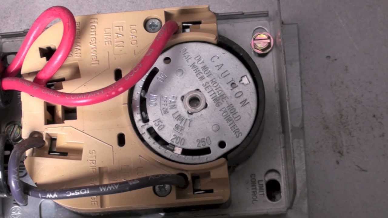
Test and Replace the Fan Limit Switch on a Furnace – HVAC How To

How The Honeywell Fan And Limit Switch Works. - Youtube - Honeywell Fan

Ceiling Fan Switch Wiring Diagram
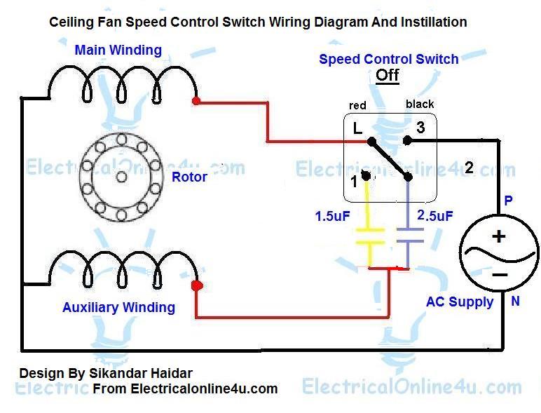
Ceiling Fan Speed Control Switch Wiring Diagram | Electrical Online 4u

ceiling fan - SELF REPARING TECHNIQUE

wiring - How can I have an exhaust fan run if either of two switches is

Honeywell Fan Limit Switch Wiring Diagram | Wiring Diagram

Ceiling Fan Speed Control Switch Wiring Diagram | Electrical Online 4u